Research interests
Numerical simulation of rock fracture and fragmentation is a topic of great interest to the mining industry. The experiences of individual miners are no longer sufficient to safely and accurately handle complex blast problems; instead, quantitative computer models are required. Recent years have seen significant investment in computational models with the primary goals of avoiding damage to structures near the blast site, and predicting the distribution of resources in the blast pile.
A large number of individual processes need to be captured for a complete simulation: ideally the detonation of explosives should be modelled by a reactive code, which must then be coupled to an elasto-plastic model of the rock to capture deformations. The latter must include the ability to model fracture, damage, and solid body heave of rock. Depending on the problem, it may also be necessary to handle the in-flight interactions of ejected rock fragments.
Reactive Euler equations
Our work always begins with the Euler equations of fluid dynamics. These describe compressible flow in terms of three conserved quantities; density, momentum, and energy,
\begin{align} \frac{\partial \rho}{\partial t} + \nabla \cdot \left(\rho \vec{u}\right) &= 0, \\ \frac{\partial \rho \vec{u}}{\partial t} + \nabla \cdot \left(\rho \vec{u} \vec{u}^T \right) + \nabla p &= \vec{0}, \\ \frac{\partial E}{\partial t} + \nabla \cdot \left( \vec{u} \left(E + p \right) \right) &= 0. \end{align}If we add a one-step Arrhenius reaction term as well as a conservation law for the mass fraction of reactant, we see a host of interesting behaviour,
\begin{align} \frac{\partial E}{\partial t} + \nabla \cdot \left( \vec{u} \left(E + p \right) \right) &= Q B \exp \left(- \frac{E_A}{R T}\right), \\ \frac{\partial \rho \lambda}{\partial t} + \nabla \cdot \left(\rho \lambda \vec{u} \right) &= -B \exp \left(- \frac{E_A}{R T}\right). \end{align}By adjusting the free parameters, we can describe a wide range of reactions, and create detonations with differing characteristics. The results below are for detonations with high activation energy, which are on the verge of not detonating at all; this results in an unstable detonation front which exhibits a cellular structure. Waves propagate transversely along the front, interacting to create hotspots, which then locally accelerate the temperature-dependent reaction.

Mock-schlieren (density gradient) capture for a detonation goverened by Arrhenius kinetics. Click for an animated version (warning: large).
If the reaction passes across a surface which has been coated with soot, a pattern corresponding to the maximum pressure at each point in space is created. The figure below shows the pattern created by this; more stable detonations create more regular cell structures.
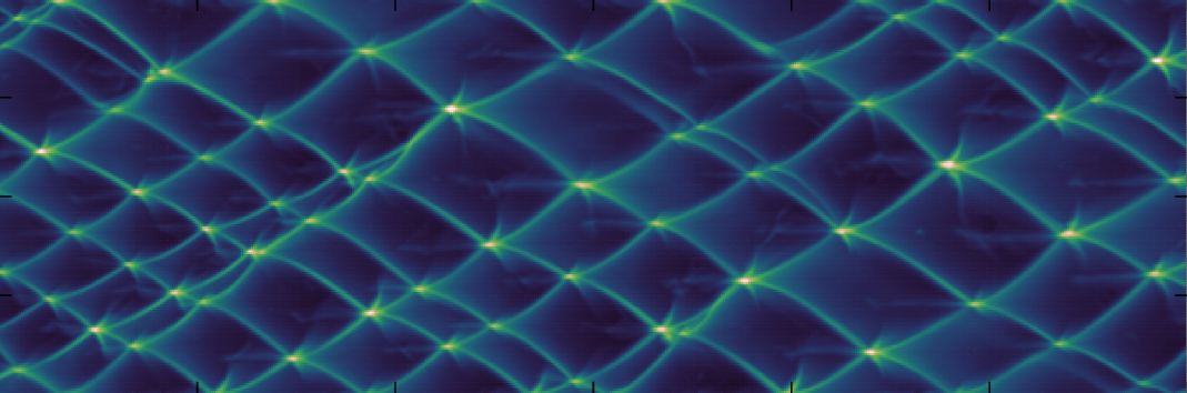
Pseudo-smoke foil results (pressure history) for a detonation goverened by Arrhenius kinetics.
Cut cell (h-box) methods
We use simulation of the transonic flow a NACA aerofoil as a validation case for embedded boundary methods. While the simulation is conceptually simple—with a Mach 0.8 inflow from the left boundary passed over the aerofoil, constant pressure outflow to the right—the test case brings out flaws in some numerical schemes. The figure below shows the density field solved for using the h-box method.
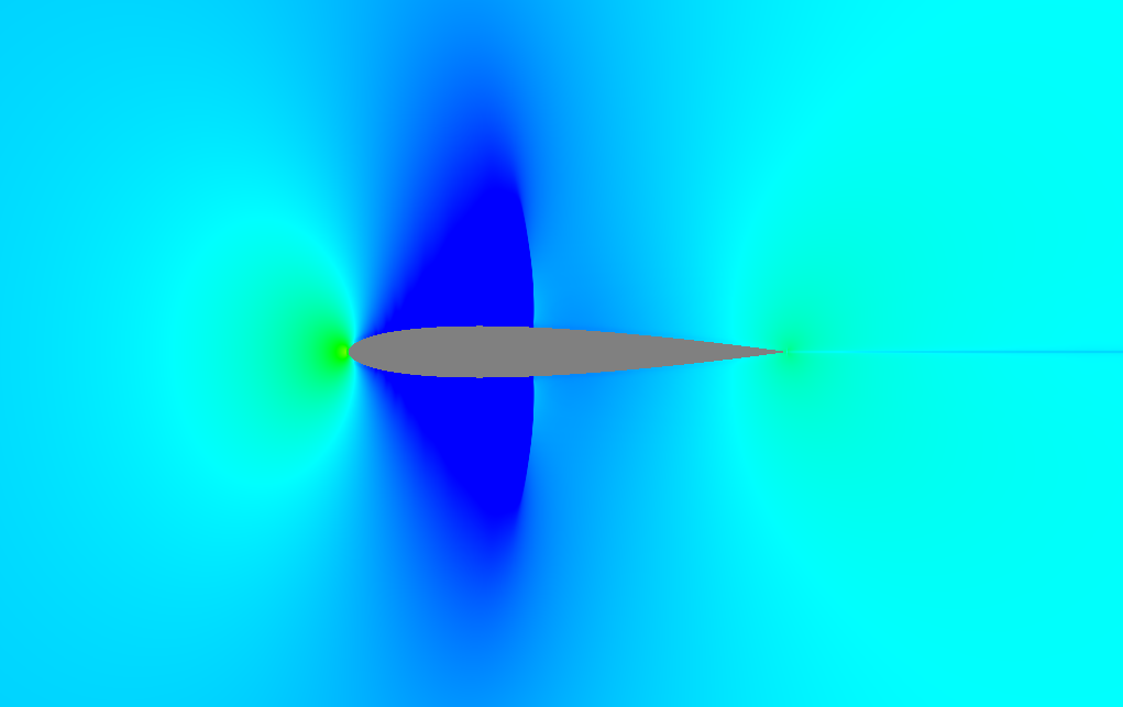
Mach 0.8 flow around a NACA 0012 aerofoil simulated using the h-box method.